3.1.8.1. Linear Transformation
This command is used to construct a linear coordinate transformation (LinearCrdTransf) object, which performs a linear geometric transformation of beam stiffness and resisting force from the basic system to the global-coordinate system.
For a two-dimensional problem:
- geomTransf Linear $transfTag <-jntOffset $dXi $dYi $dXj $dYj>
For a three-dimensional problem:
- geomTransf Linear $transfTag $vecxzX $vecxzY $vecxzZ <-jntOffset $dXi $dYi $dZi $dXj $dYj $dZj>
Argument |
Type |
Description |
|---|---|---|
$transfTag |
integer |
integer tag identifying transformation |
$vecxzX $vecxzY $vecxzZ |
float |
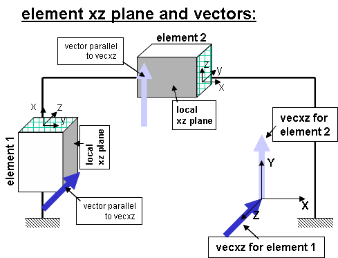
X, Y, and Z components of vecxz, the vector used to define the local x-z plane of the local-coordinate system. The local y-axis is defined by taking the cross product of the vecxz vector and the x-axis. These components are specified in the global-coordinate system X,Y,Z and define a vector that is in a plane parallel to the x-z plane of the local-coordinate system. These items need to be specified for the three-dimensional problem. |
$dXi $dYi $dZi |
float |
joint offset values – offsets specified with respect to the global coordinate system for element-end node i (optional, the number of arguments depends on the dimensions of the current model). |
$dXj $dYj $dZj |
float |
joint offset values – offsets specified with respect to the global coordinate system for element-end node j (optional, the number of arguments depends on the dimensions of the current model). |
A refresher on Euclidean Geometry and Coordinate Systems:
A single vector may be defined by two points. It has length, direction, and location in space. When this vector is used to define a coordinate axis, only its direction is important. Now any 2 vectors, \(V_r\) and \(V_s\), not parallel, define a plane that is parallel to them both. The cross-product of these vectors define a third vector, \(V_t\), that is perpendicular to both \(V_r\) and \(V_s\) and hence normal to the plane: \(V_t = V_r . V_s\).
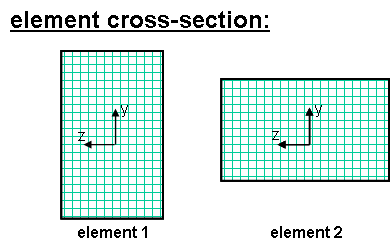
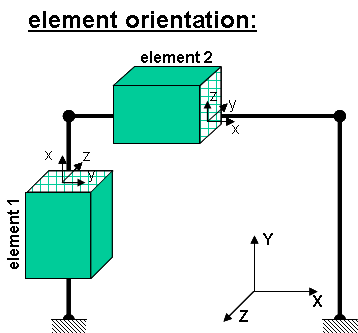
The element coordinate system is specified as follows:
The x-axis is a vector given by the two element nodes; The vector vecxz is a vector the user specifies that must not be parallel to the x-axis. The x-axis along with the vecxz Vector define the xz plane. The local y-axis is defined by taking the cross product of the x-axis vector and the vecxz vector (\(V_y = V_{xz} . V_x\)). The local z-axis is then found simply by taking the cross product of the y-axis and x-axis vectors (\(V_z = V_x . V_y\)). The section is attached to the element such that the y-z coordinate system used to specify the section corresponds to the y-z axes of the element.
Fig. 3.1.8.1 Element Orentation
Fig. 3.1.8.2 Rigid Element Offsets
Note
When in 2D, local x and y axes are in the X-Y plane, where X and Y are global axes. Local x axis is the axis connecting the two element nodes, and local y and z axes follow the right-hand rule (e.g., if the element is aligned with the positive Y axis, the local y axis is aligned with the negative X axis, and if the element is aligned with the positive X axis, the local y axis is aligned with the positive Y axis). Orientation of local y and z axes is important for definition of the fiber section.
Example:
Tcl Code
#Element 1 : tag 1 : vecxZ = zaxis
geomTransf Linear 1 0 0 -1

#Element 2 : tag 2 : vecxZ = y axis
geomTransf Linear 2 0 1 0

#If there was a rigid offset at the top of element 1:
geomTransf Linear 1 0 0 -1 -jntOffset 0.0 0.0 0.0 0.0 -$Offset 0.0
Python Code
#Element 1 : tag 1 : vecxZ = zaxis
geomTransf('Linear', 1, 0, 0, -1)

#Element 2 : tag 2 : vecxZ = y axis
geomTransf('Linear', 2, 0, 1, 0)

#If there was a rigid offset at the top of element 1: (offset is a variable that the offset value has been stored in)
geomTransf('Linear', 3, 0, 0, -1,'-jntOffset',0.0, 0.0, 0.0, 0.0, offset, 0.0)