3.1.5.10. SteelFractureDI Material
This command is used to construct a uniaxial Giuffre-Menegotto-Pinto steel material object similar to Steel02 but equipped with a real-time stress-based fracture criterion and a post-fracture constitutive law to simulate the behavior of steel flates after fracture.
- uniaxialMaterial SteelFractureDI $matTag $Fy $FyC $E $b $R0 $cR1 $cR2 $a1 $a2 $a3 $a4 $sigcr $beta $sigmin $FI_lim
Argument |
Type |
Description |
|---|---|---|
$matTag |
integer |
integer tag identifying material |
$Fy |
float |
tension yield strength |
$FyC |
float |
Compression yield strength |
$E0 |
float |
initial elastic tangent |
$b |
float |
strain-hardening ratio (ratio between post-yield tangent and initial elastic tangent) |
R0 $CR1 $CR2 |
3 float |
parameters to control the transition from elastic to plastic branches. |
$a1 |
float |
isotropic hardening parameter. (optional: default = 0.0). see Steel02 documentation. |
$a2 |
float |
isotropic hardening parameter (optional: default = 1.0). see Steel02 documentation. |
$a3 |
float |
isotropic hardening parameter. (optional: default = 0.0). see Steel02 documentation. |
$a4 |
float |
isotropic hardening parameter. (optional: default = 1.0). see Steel02 documentation. |
$sigInit |
float |
critical stress for fracture criterion |
$beta |
float |
asymmetry factor for fracture criterion. See notes |
$sigmin |
float |
minimum stress to accumulate damage in the frature index calculation. See notes |
$FI_lim |
float |
Limit of the fracture index to trigger fracture. See notes |
Note
$beta = 0 Ignores any reduction in the fracture index from compressive excursions.
$beta = 1 Maximum reduction in the fracture index from compressive excursions.
$sigmin: any stress with an absolute value below sigmin will be ignored when computing the fracture index. $sigmin is analogous to the endurance limit in classical fatigue-fracture theory.
$FI_lim: The material calculates a fracture index (FI) at every load increment and when that value exceeds $FI_lim, any tensile capacity drops to zero and the response of the material corresponds to the post-fracture constitutive law.
Recommended values for steel behavior: $R0=between 10 and 20, $cR1=0.925, $cR2=0.15, $a1=0.08, $a2=1.00, $a3=0.08, $a4=1.00
Recommended values for fracture criterion (calibrated only to welded flanges in beam-to-column connections): $sigcr=compute based on material toughness (CVN), weld defect size (a0), and plate size (see [GalvisEtAl12022] for equations), $beta=0.8 for pre-Northridge bottom flange or $beta=0.5 otherwise, $sigmin=0.4Fy_basemetal, and $FI_lim=1.0. The aleatory uncertainty in fracture prediction can be included by sampling the value of $FI_lim from a lognormal or Weibull distribution with median=1.0 and COV=0.25 for pre-Northridge connections and COV=0.35 for post-Northridge connections.
POST-FRACTURE CONSTITUTIVE LAW
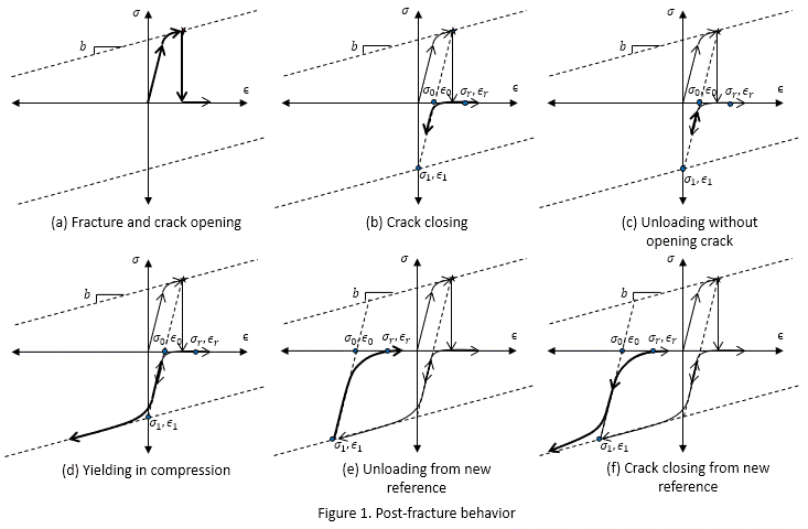
SteelFractureDI model uses the post-fracture constitutive law schematically described in Figure 1. Figure 1a depicts the instant of fracture when the stress drops to zero and remains there as long as the strain is increasing to simulate the opening of the crack. To model the potential crack closing that could occur after reversing the strain, the post-fracture constitutive law assumes a smooth curvilinear transition towards compressive stresses. This transition is controlled by four transient variables: \(ϵ_r\), \(ϵ_0\), \(ϵ_1\), and \(σ_1\). \(ϵ_r\) is the maximum strain value to develop compressive stresses, \(ϵ_0\) is the strain value at full contact of the fracture surface, \(ϵ_1\) is the theoretical yielding strain in compression, and \(σ_1\) is the compressive stress associated with \(ϵ_1\) in the yield surface. Figure 1b shows the transient variables immediately after fracture. The trajectory of the compressive stress is depicted with a curvilinear arrow pointing downward. Figure 1c shows that a small reversal of strain causes an elastic reduction of compressive stress. This elastic response is simulated by keeping the same value of the transient variables. When the compressive excursion is large enough to cause yielding in compression (Figure 1d), the reference points are updated as soon as the strain reverses towards unloading as depicted in Figure 1e. This update of the transient variables simulates the plastic deformations on the surface of the fractured flange; therefore, contact occurs at a different location. Figure 1f shows a subsequent cycle of the crack closing at the new location of the fracture surface using the updated transient variables.

FRACTURE CRITERION
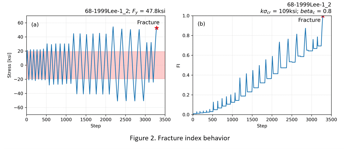
SteelFractureDI is equipped with a stress-based fracture criterion that explicitly captures the fatigue damage that is accumulated with repeated cycles and that ultimately causes fracture. This is done using a real-time fracture index (FI) that compares the effective cummulative stress demand and the cummulative stress capacity. The capacity is a fixed value calles $sigcr that can be calculated based on experimental data ([GalvisEtAl12022] presents equations for modeling welded flanges in steel beam-to-column connections). The demand correspond to the difference of the tensile and compressive excursions. The fracture criterion only considers large excursions, exceding $sigmin, to accumulate damage. Figure 2a shows an example stress history and a red bad to denote the portion of the excursions that are not considered in the FI calculation. Figure 2b shows the evolution of the FI for the stress history shown in Figure 2a. The FI function shows a monotonic increasing trend representing the damage caused by tensile excursions that is not healed by the subsequent compressive excursion. The higher-frequency spikes correspond to the recoverable damage when the stress reverses.

Example
The following is used to construct a SteelFractureDI material with a tag of 1, a yield strength of 60.0, an initial tangent stiffness, E, of 30000.0, a strain-hardening ratio of 0.02, a sigma critical of 120, an asymmetry factor of 0.8, a minimum stress for damage accumulation of 20.0, and a fracture index limit of 1.0.
Tcl Code
uniaxialMaterial SteelFractureDI 1 60.0 60.0 30000.0 0.02 20.0 .925 .15 0.08 1.00 0.08 1.00 120 0.8 20 1.0
Python Code
uniaxialMaterial('SteelFractureDI', 1, 60.0, 60.0, 30000.0, 0.02, 20.0, .925, .15, 0.08, 1.00, 0.08, 1.00, 120, 0.8, 20, 1.0)
Code Developed by: |Francisco A. Galvis|