3.1.10.51. Joint2D Element
This command is used to construct a two-dimensional beam-column-joint element object. The two dimensional beam-column joint is idealized as a parallelogram shaped shear panel with adjacent elements connected to its mid-points. The midpoints of the parallelogram are referred to as external nodes. These nodes are the only analysis components that connect the joint element to the surrounding structure.
3.1.10.51.1. Command Lines
TCL:
- element Joint2D $eleTag $Node1 $Node2 $Node3 $Node4 $NodeC <$Mat1 $Mat2 $Mat3 $Mat4> $MatC $LrgDspTag <-damage <Dmg1 Dmg2 Dmg3 Dmg4> DmgC>
Python:
- element('Joint2D', eleTag, Node1, Node2, Node3, Node4, NodeC, <Mat1, Mat2, Mat3, Mat4>, MatC, LrgDspTag, <'-damage', DmgTag>, <'-damage', Dmg1 Dmg2 Dmg3 Dmg4 DmgC>)
where:
Argument |
Type |
Description |
|---|---|---|
$eleTag |
integer |
Unique element object tag |
$Node1 … $Node4 |
integer |
Node tags indicating four external nodes where the joint element is connected to the adjoining beam-column element |
$NodeC |
integer |
Node tag indicating the central node of beam-column joint (the tag is used to generate the internal node, thus, the node should not exist in the domain or be used by any other node) |
$Mat1 … $Mat4 |
integer |
Uniaxial material tags for interface rotational spring at the specified node. Use a zero tag to indicate the case that a beam-column element is rigidly framed to the joint. (optional) |
$MatC |
integer |
Uniaxial material tag for rotational spring of the central node that describes shear panel behavior |
$LrgDspTag |
integer |
an integer indicating the flag for considering large deformations:
0 - for small deformations and constant geometry1 - for large deformations and time varying geometry2 - for large deformations, time varying geometry and length correction |
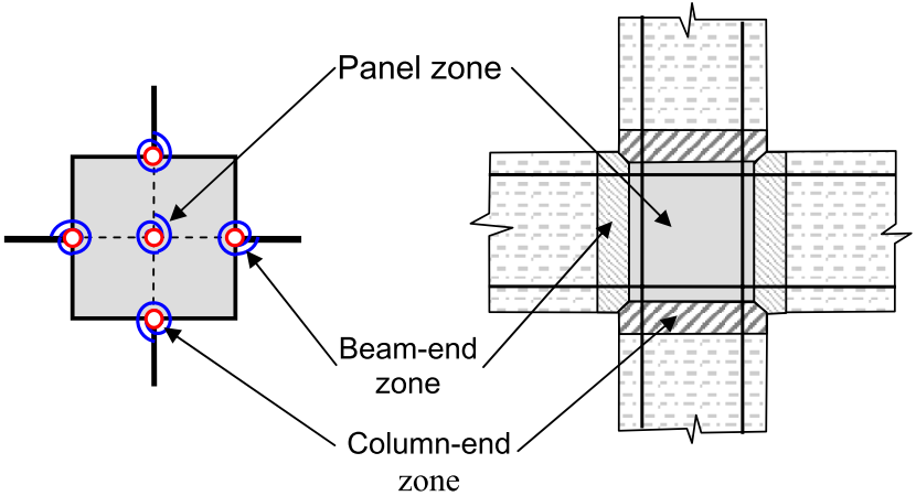
Fig. 3.1.10.26 Joint2D Element: The joint zones represented by rotational springs.
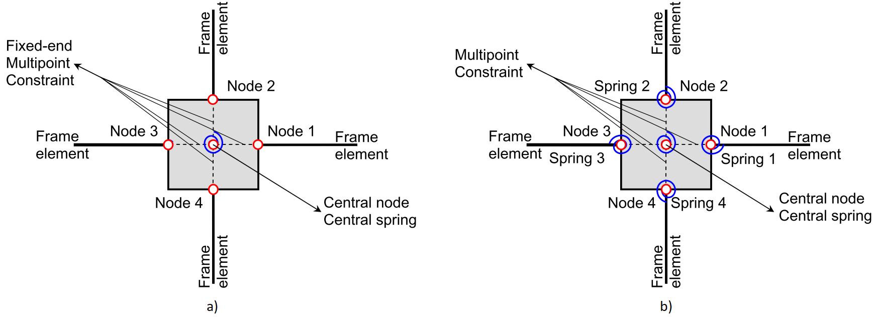
Fig. 3.1.10.27 Joint2D Element: Graphic representation of the internal components of the element a) with 1 rotational spring and b) with 5 rotational springs.
Notes
3.1.10.51.2. Output Recorders
The valid inquires to the Joint2D beam-to-column joint finite element include:
centralNode: Displacement components of the central node.
deformation: Interface rotations and shear panel deformation.
force: Nodal moments and the joint panel shear-equivalent moment.
size: Length of the main chord (element size).
stiffness: Joint element stiffness matrix.
defoANDforce: Joint deformation components followed by the nodal moments.
3.1.10.51.3. Examples
Command Lines
Example 1
The following example constructs constructs a Joint2D joint element with element tag 12, that is connected to nodes 1, 2, 3, 4. The element will generate a center node with tag 112, and it uses the uniaxial material object with tag 10 as the shear panel rotational spring. This joint element does not have rotational springs at external nodes and does not include large deformations.
1.1. Tcl
element Joint2D 12 1 2 3 4 112 10 0;
1.2. Python
element('Joint2D', 12, 1, 2, 3, 4, 112, 10, 0)
Example 2
The following example constructs constructs a Joint2D joint element with element tag 13, that is connected to nodes 5, 6, 7, 8. The element will generate a center node with tag 113, and it uses the uniaxial material object with tag 11 for nodes 5 and 7, and rigid connections for nodes 6 and 8 to prevent member end rotations. The shear panel behavior is modeled with uniaxial material with tag 10. The generated multipoint constraint matrices will be time varying to cover large deformations and the nodal positions will be corrected to maintain the initial joint size.
2.1. Tcl
element Joint2D 13 5 6 7 8 113 11 0 11 0 10 2;
2.2. Python
element('Joint2D', 13, 5, 6, 7, 8, 113, 11, 0, 11, 0, 10, 2)
References
More information available in the following reference:
Arash Altoontash, 2004, “Simulation and damage models for performance assessment of reinforced concrete beam-column joints”, PhD Dissertation, Stanford University, California, USA. [URL].
Code developed by: Arash Altoontash