3.1.10.26. Displacement-Based Beam Element (Asymmetric Sections)
This command is used to construct a DispBeamColumnAsym3d element object, which is suitable for modeling flexural, flexural-torsionl and torsional buckling of members with asymmetric section such as angles and tees. It can also be used to model members with doublely-symmetric sections. The corotational total Lagrangian method is used to capture the axial-flexural-torsional interaction behavior, while the fiber section method is used for modeling material nonlinearity. The fibers and coordinates of the shear center should be defined with respect to the principal axes of the section. Note that warping is not considered in this element.
For more information about the element formulation, please refer to the references at the end of this page.
TCL ELEMENT COMMAND
For 3D problems:
- element dispBeamColumnAsym $eleTag $iNode $jNode $numIntgrPts $secTag $transfTag <-shearCenter $y0 $z0> <-integration integrType>
The required arguments are:
Argument |
Type |
Description |
|---|---|---|
$eleTag |
integer |
unique element object tag |
$iNode $jNode |
integer |
end nodes |
$numIntgrPts |
integer |
total number of integration points |
$secTag |
integer |
section tag |
$transfTag |
integer |
identifier for previously-defined coordinate-transformation (CrdTransf) object |
The optional arguments are:
Argument |
Sub-argument |
Type |
Description |
|---|---|---|---|
-shearCenter |
used to define coordinates of the shear center |
||
$y0 $z0 |
float |
coordinates of the shear center S w.r.t. the centroid C and the principal axes (Fig. 1) (default y0=z0=0.0) |
|
-integration |
used to select integration type |
||
integrType |
string |
numerical integration type, options are Lobatto, Legendre, Radau, NewtonCotes, Trapzoidal (default = Lobatto) |
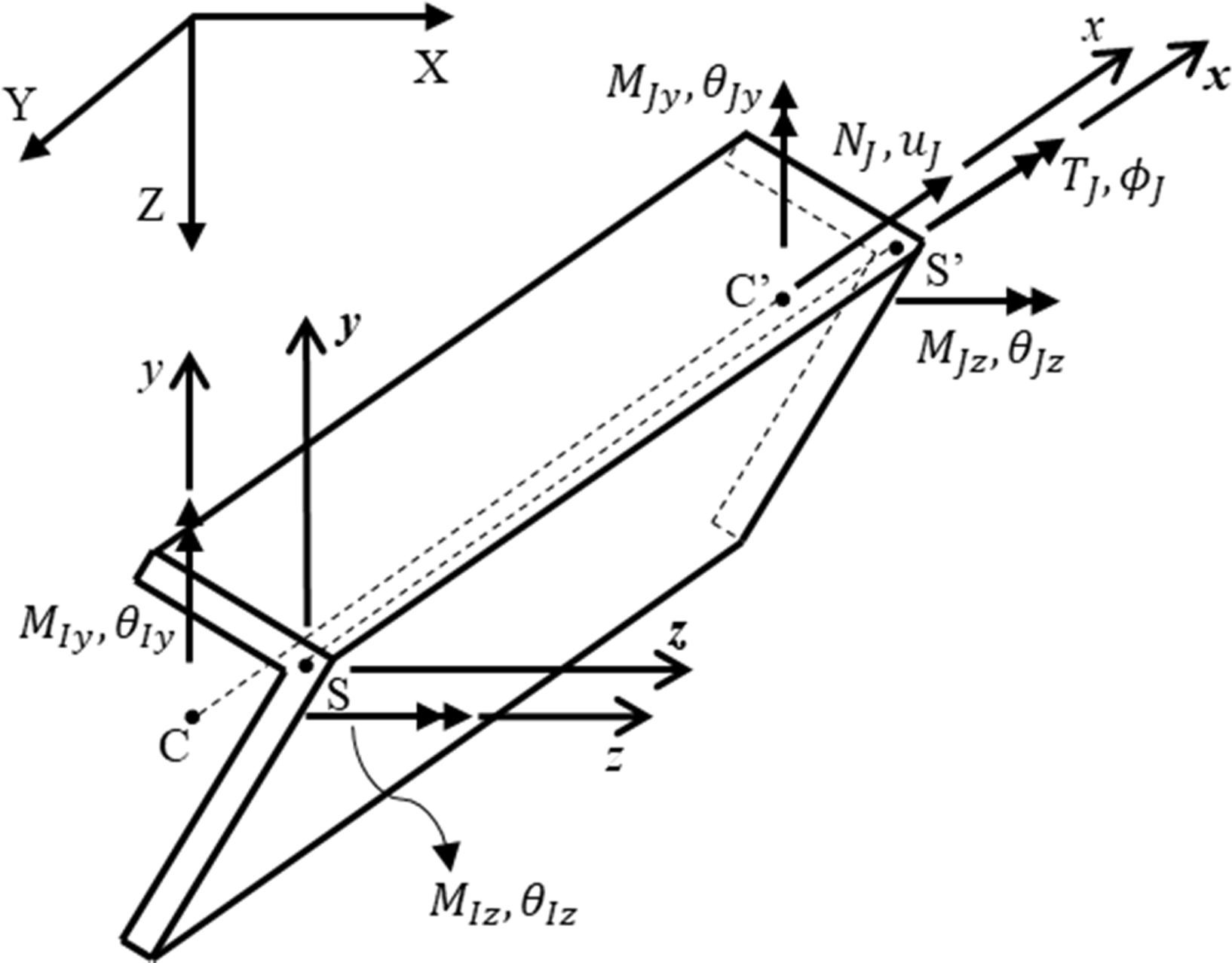
Fig. 3.1.10.12 Fig. 1: Coordinate systems for members with asymmetric sections (CC’: centroidal axis, SS’: shear center axis)
PYTHON ELEMENT COMMAND
For 3D problems:
- element('dispBeamColumnAsym', $eleTag, $iNode, $jNode, $transfTag, $integrTag, '-shearCenter', $y0, $z0)
The required arguments are:
Argument |
Type |
Description |
|---|---|---|
$eleTag |
integer |
unique element object tag |
$iNode $jNode |
integer |
end nodes |
$transfTag |
integer |
identifier for previously-defined coordinate-transformation (CrdTransf) object |
$integrTag |
integer |
identifier for previously-defined beam integration object |
The optional arguments are:
Argument |
Sub-argument |
Type |
Description |
|---|---|---|---|
-shearCenter |
used to define coordinates of the shear center |
||
$y0 $z0 |
float |
coordinates of the shear center S w.r.t. the centroid C and the principal axes (Fig. 1) |
- NOTES:
For asymmetric sections, y0 and z0 should be passed to the fiber section object using the FiberAsym command. In Tcl, it is like: section FiberAsym $secTag $y0 $z0 -GJ $GJ {…}.
Example
The following codes construct Example 4.6 in Du and Hajjar (2021). The libraries can be found from the OpenSeesWiki. The definition of the angle section (L3x2x0_25.tcl) is not provided here, but the mesh information is shown in the following Python code. Note that in order for clarity the mesh here is coarser than that used in Du and Hajjar (2021).
Tcl Code
# --------------------------------------------------------------------------------------------------
# 3D Steel L-section beam subjected to compressive load on shear center
# Xinlong Du, 9/25/2019
# Displacement-based beam-column element for asymmetric sections
# --------------------------------------------------------------------------------------------------
set systemTime [clock seconds]
puts "Starting Analysis: [clock format $systemTime -format "%d-%b-%Y %H:%M:%S"]"
set startTime [clock clicks -milliseconds];
# SET UP ----------------------------------------------------------------------------
wipe;                             # clear memory of all past model definitions
model BasicBuilder -ndm 3 -ndf 6; # Define the model builder, ndm=#dimension, ndf=#dofs
set dataDir Data;                 # set up name of data directory
file mkdir $dataDir;                      # create data directory
source LibUnits.tcl;                      # define units
source DisplayPlane.tcl;          # procedure for displaying a plane in model
source DisplayModel3D.tcl;                # procedure for displaying 3D perspectives of model
# define GEOMETRY ------------------------------------------------------------------
#Nodes, NodeNumber, xCoord, yCoord, zCoord
for {set i 1} {$i<8} {incr i 1} {
        node $i [expr -9.2+9.2*$i] 0 0;
}
# ------ define boundary conditions
# NodeID,dispX,dispY,dispZ,rotX,RotY,RotZ
fix 1  1 1 1 1 1 1;
set StartNode 1;
set EndNode 7;
# Define  SECTIONS -------------------------------------------------------------
set ColSecTag 1
# define MATERIAL properties
set Es [expr 27910.0*$ksi];               # Steel Young's Modulus
set nu 0.3;
set Gs [expr $Es/2./[expr 1+$nu]];  # Torsional stiffness Modulus
set matID 1
uniaxialMaterial Elastic $matID $Es;
set J [expr  0.02473958*$in4]
set GJ [expr $Gs*$J]
set z0 [expr 0.64625474*$in];
set y0 [expr -0.68720012*$in];
source L3x2x0_25.tcl;
# define ELEMENTS-----------------------------------------------------------------------------------------------
set IDColTransf 1; # all members
set ColTransfType Corotational;           # options for columns: Linear PDelta Corotational
geomTransf $ColTransfType  $IDColTransf 0 0 1;    #define geometric transformation: performs a corotational geometric transformation
set numIntgrPts 2;        # number of Gauss integration points
for {set i 1} {$i<$EndNode} {incr i 1} {
set elemID $i
set nodeI $i
set nodeJ [expr $i+1]
element dispBeamColumnAsym $elemID $nodeI $nodeJ $numIntgrPts $ColSecTag $IDColTransf -shearCenter $y0 $z0;
}

# Define RECORDERS -------------------------------------------------------------
recorder Node -file $dataDir/DispDB6.out -time -node $EndNode -dof 1 2 3 4 5 6 disp;                      # displacements of middle node
recorder Node -file $dataDir/ReacDB6.out -time -node $StartNode -dof 1 2 3 4 5 6 reaction;                # support reaction

# Define DISPLAY -------------------------------------------------------------
DisplayModel3D DeformedShape;      # options: DeformedShape NodeNumbers ModeShape

# define Load-------------------------------------------------------------
set N 15.0;
pattern Plain 2 Linear {
  # NodeID, Fx, Fy, Fz, Mx, My, Mz
  load $EndNode -$N 0 0 0 0 0;
}

# define ANALYSIS PARAMETERS------------------------------------------------------------------------------------
constraints Plain; # how it handles boundary conditions
numberer Plain;      # renumber dof's to minimize band-width
system BandGeneral;# how to store and solve the system of equations in the analysis
test NormDispIncr 1.0e-08 1000; # determine if convergence has been achieved at the end of an iteration step
#algorithm NewtonLineSearch;# use Newton's solution algorithm: updates tangent stiffness at every iteration
algorithm Newton;
set Dincr -0.01;
                               #Node,  dof, 1st incr, Jd, min,   max
integrator DisplacementControl $EndNode 1   $Dincr     1  $Dincr -0.01;
analysis Static   ;# define type of analysis static or transient
analyze 7000;
puts "Finished"
#--------------------------------------------------------------------------------
set finishTime [clock clicks -milliseconds];
puts "Time taken: [expr ($finishTime-$startTime)/1000] sec"
set systemTime [clock seconds]
puts "Finished Analysis: [clock format $systemTime -format "%d-%b-%Y %H:%M:%S"]"
Python Code
# --------------------------------------------------------------------------------------------------
# 3D Steel L-section beam subjected to compressive load on shear center
# Xinlong Du, 5/31/2021
# Displacement-based beam-column element for asymmetric sections
# --------------------------------------------------------------------------------------------------
#from openseespy.opensees import *
from opensees import *
import numpy as np
import matplotlib.pyplot as plt
import os
# SET UP ----------------------------------------------------------------------------
wipe()
model('basic', '-ndm', 3, '-ndf', 6)
# units
inch = 1.0;
kip = 1.0;
sec = 1.0;
# Dependent units
sq_in = inch*inch;
ksi = kip/sq_in;
ft = 12.0*inch;
in4 = inch**4;
dataDir = 'Data';
#os.mkdir(dataDir);
# define GEOMETRY ------------------------------------------------------------------
for i in range(1,8):
    node(i,-9.2+9.2*i,0.0,0.0)
# define boundary conditions
fix(1, 1, 1, 1, 1, 1, 1);
StartNode = 1;
EndNode = 7;
# Define  SECTIONS -------------------------------------------------------------
ColSecTag = 1;
# define MATERIAL properties
Es = 27910.0*ksi;         # Steel Young's Modulus
nu = 0.3;
Gs = Es/2./(1+nu);  # Torsional stiffness Modulus
matID = 1;
uniaxialMaterial('Elastic', matID, Es);
# SECTION properties
J = 0.02473958*in4;
Gj = Gs*J;
z0 = 0.64625474*inch;
y0 = -0.68720012*inch;
section('FiberAsym', ColSecTag, y0, z0, '-GJ', Gj);
fiber(-0.6872,  0.6463, 0.0625, matID);
fiber(-0.5864,  0.4175, 0.0625, matID);
fiber(-0.4857,  0.1887, 0.0625, matID);
fiber(-0.3849, -0.0401, 0.0625, matID);
fiber(-0.2841, -0.2689, 0.0625, matID);
fiber(-0.1834, -0.4977, 0.0625, matID);
fiber(-0.0826, -0.7265, 0.0625, matID);
fiber( 0.0182, -0.9553, 0.0625, matID);
fiber( 0.1189, -1.1841, 0.0625, matID);
fiber( 0.2197, -1.4129, 0.0625, matID);
fiber( 0.3205, -1.6417, 0.0625, matID);
fiber( 0.4212, -1.8705, 0.0625, matID);
fiber( -0.4584, 0.7470, 0.0625, matID);
fiber( -0.2296, 0.8478, 0.0625, matID);
fiber( -0.0008, 0.9486, 0.0625, matID);
fiber( 0.2280,  1.0493, 0.0625, matID);
fiber( 0.4568,  1.1501, 0.0625, matID);
fiber( 0.6856,  1.2509, 0.0625, matID);
fiber( 0.9143,  1.3516, 0.0625, matID);
# define ELEMENTS-----------------------------------------------------------------------------------------------
# set up geometric transformations of element
ColTransfTag = 1; # all members
vecxz=[0.0, 0.0, 1.0];
geomTransf('Corotational', ColTransfTag, *vecxz); #define geometric transformation: performs a corotational geometric transformation
# Define Beam-Column Elements
numIntgrPts = 2;  # number of Gauss integration points
beamIntTag = 1;
beamIntegration("Legendre",  beamIntTag, ColSecTag, numIntgrPts)
for i in range (1,EndNode):
    elemID = i;
    nodeI = i;
    nodeJ = i+1;
    element('dispBeamColumnAsym', elemID, *[nodeI, nodeJ], ColTransfTag, beamIntTag,'-shearCenter', *[y0, z0]);
# Define RECORDERS -------------------------------------------------------------
recorder('Node', '-file', f'{dataDir}/DispDB6.out', '-time', '-node', *[EndNode], '-dof', *[1, 2, 3, 4, 5, 6,], 'disp');
recorder('Node', '-file', f'{dataDir}/ReacDB6.out', '-time', '-node', *[StartNode], '-dof', *[1, 2, 3, 4, 5, 6,], 'reaction');
#-------------------------------------------------------------
N = 15.0;
timeSeries('Linear',1);
pattern('Plain', 2, 1);
load(EndNode, *[-N, 0.0, 0.0, 0.0, 0.0, 0.0]);
# define ANALYSIS PARAMETERS
#------------------------------------------------------------------------------------
constraints('Plain'); # how it handles boundary conditions
numberer('Plain');           # renumber dof's to minimize band-width
system('BandGeneral');# how to store and solve the system of equations in the analysis
test('NormDispIncr', 1.0e-08, 1000); # determine if convergence has been achieved at the end of an iteration step
algorithm('Newton');
Dincr = -0.01;
                                  #Node,  dof, 1st incr, Jd,  min,   max
integrator('DisplacementControl', EndNode, 1,   Dincr,    1,  Dincr, -0.01);
analysis('Static');       # define type of analysis static or transient
analyze(7000);
print('Finished')
REFERENCES:
Du, X., & Hajjar, J. (2021). Three-dimensional nonlinear displacement-based beam element for members with angle and tee sections. Engineering Structures, 239, 112239.
Code developed by: Xinlong Du |dxl| (Northeastern University).