3.1.10.31. TripleFrictionPendulumX Element
This command is used to construct the TripleFrictionPendulumX element [KimConstantinou2022] [KimConstantinou2023] [KimConstantinou2024] object, which is an extension of the TripleFrictionPendulum element [DaoEtAl2013] with added capability for accounting for heating effects on the frictional behavior of triple friction pendulum isolators. The horizontal behavior of the element is achieved by the series model, which consists of properly combined hysteretic/frictional and multidirectional gap elements.
Three main modifications in the TripleFrictionPendulumX element include: 1) computation of the displacement and velocity histories at each of the four sliding interfaces of the isolator, 2) computation of the temperature history at each sliding interface, and 3) accounting for the dependency of the coefficient of friction on the instantaneous temperature at each sliding interface. The factorized friction model used in OpenSees element FPBearingPTV [KumarEtAl2015] is used to account for the effects of pressure, velocity, and temperature on the friction coefficients at each sliding surfaces, with the latter effect expanded to include more possible friction-temperature laws. In OpenSees element FPBearingPTV, the friction coefficient is given by equations (1) to (4) in which \(\mu_{ref}\) is the reference high speed coefficient of friction at the initial time \(t = 0\), initial temperature \(T_{0} = 20℃\) and initial pressure \(p_{0}\), \(a\) is velocity rate parameter \((= 100sec/m)\), \(p\) is the apparent pressure, and \(v\) is the amplitude of the velocity.
In the TripleFrictionPendulumX element, the temperature-dependency of the friction coefficient was expanded beyond the single case described by equation (4). Specifically, two additional cases were added, described by equations (5) and (6). Figure 1 depicts the coefficient \(k_T\) as function of temperature for the three cases. In the three cases, the value of coefficient \(k_T\) drops from the unity at the normal temperature to 1/3, 1/2 or 2/3 at approximately the temperature of \(200℃\).
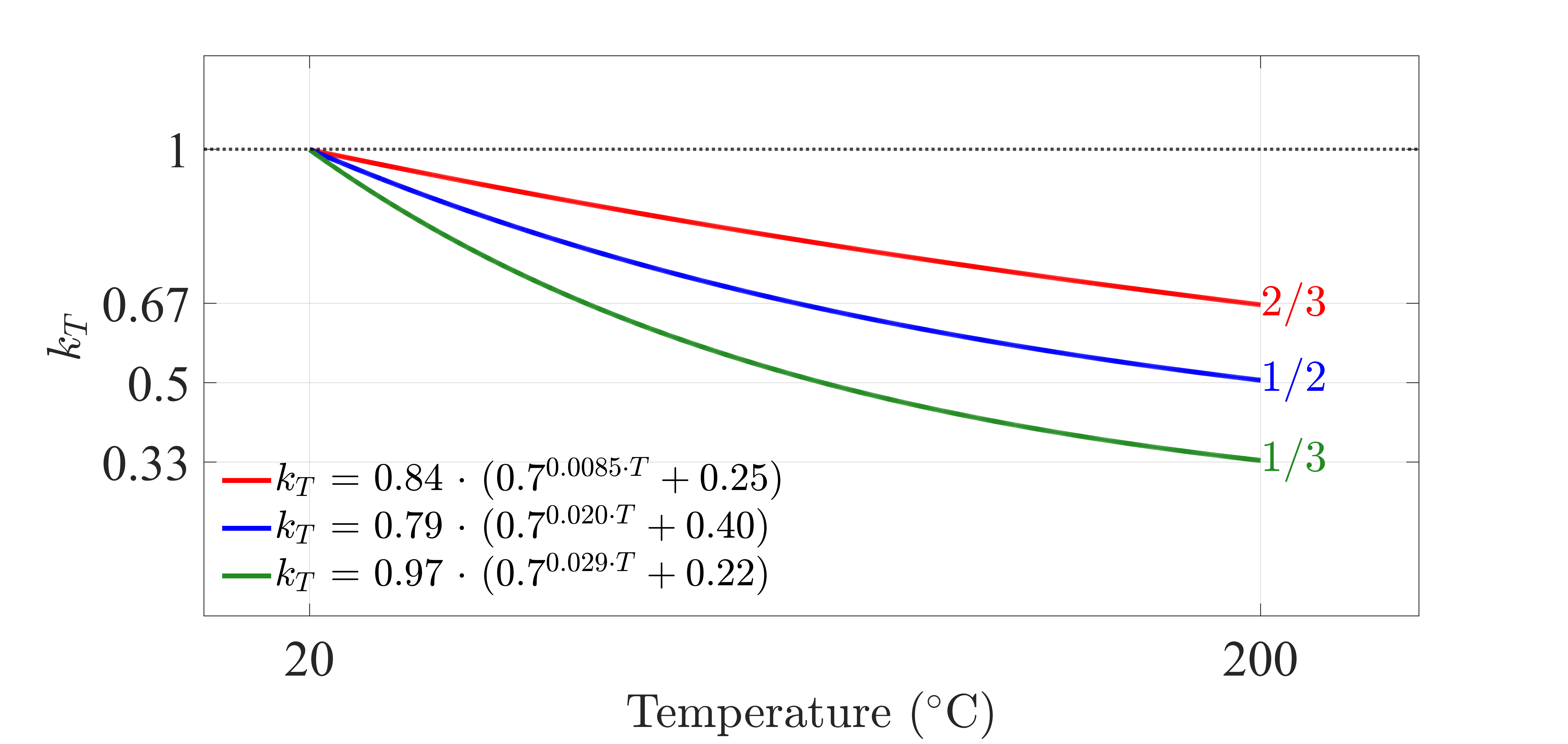
Fig. 3.1.10.30 Figure 1. Friction Coefficient-Temperature Relationships in TripleFrictionPendulumX element
The existing element TripleFrictionPendulumX-version 1 is based on a theory in which the concave plates of the isolator are assumed to be infinite in thickness. The new version (version 2.0) of the TripleFrictionPendulumX element provides an option for specifying finite thickness (the thicknesses may be the same or may be different) for both concave plates, which are presumed to be bounded by an insulating medium (for example, the case of a steel plate on a concrete foundation). Finite thickness, and particularly small thickness over an insulated medium, causes an increase in temperature [KimConstantinou2024]. Figure 2 illustrates the two options of heat conduction theories for temperature calculations at the sliding surfaces and over the depth of the concave plates.
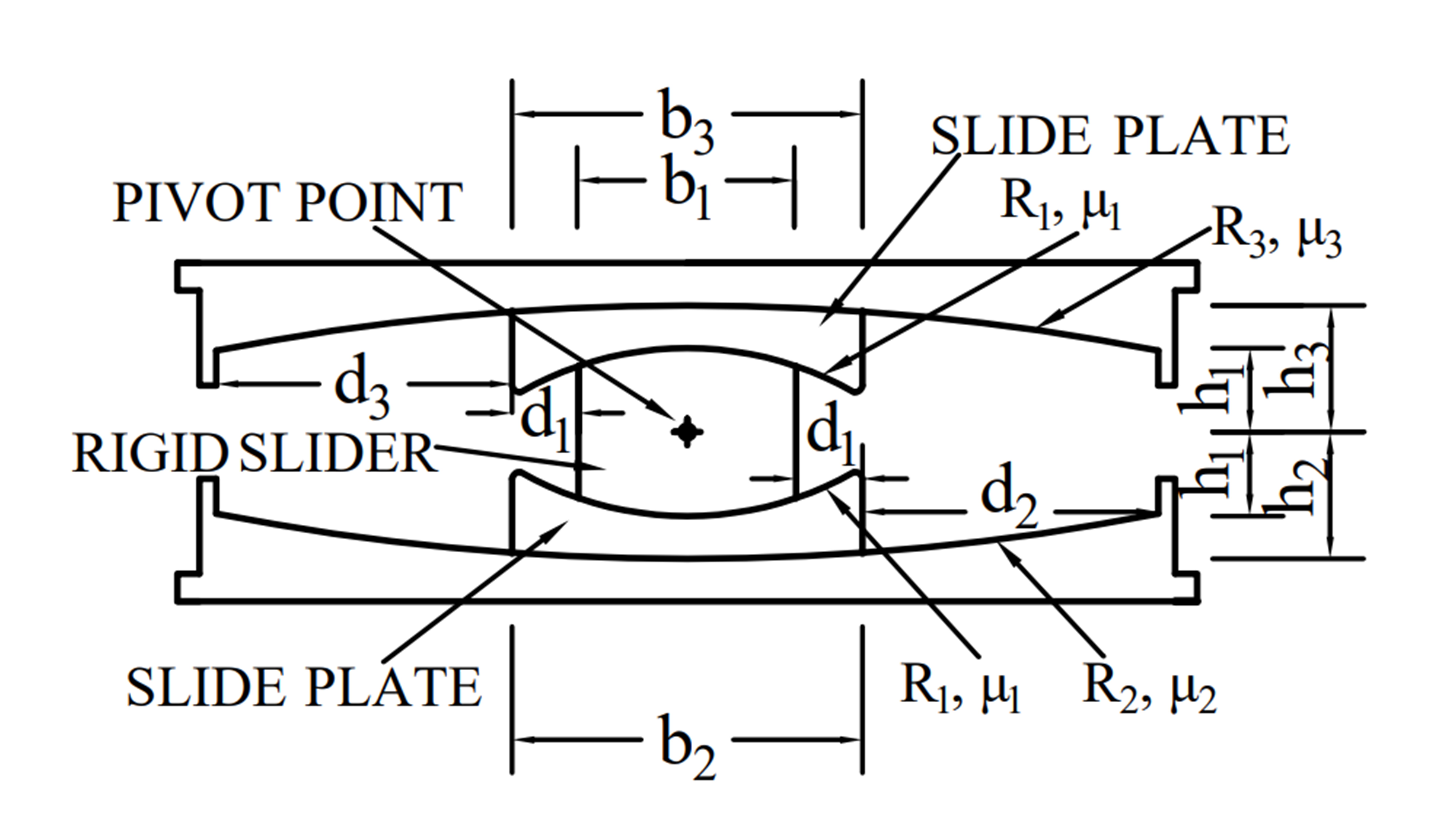
Fig. 3.1.10.31 Figure 2. Options of heat conduction solutions for temperature calculations at sliding surface and at depth in TripleFrictionPendulumX element; (a) Theory based indefinite half space, (b) Theory based on plates of finite depth over insulated space.
The updated recorder “Parameters” of the element provides options to obtain histories of temperature at the two main sliding surfaces and over depth based on two different heat conduction solutions.
For more information about the element formulation, please refer to the references at the end of this page.
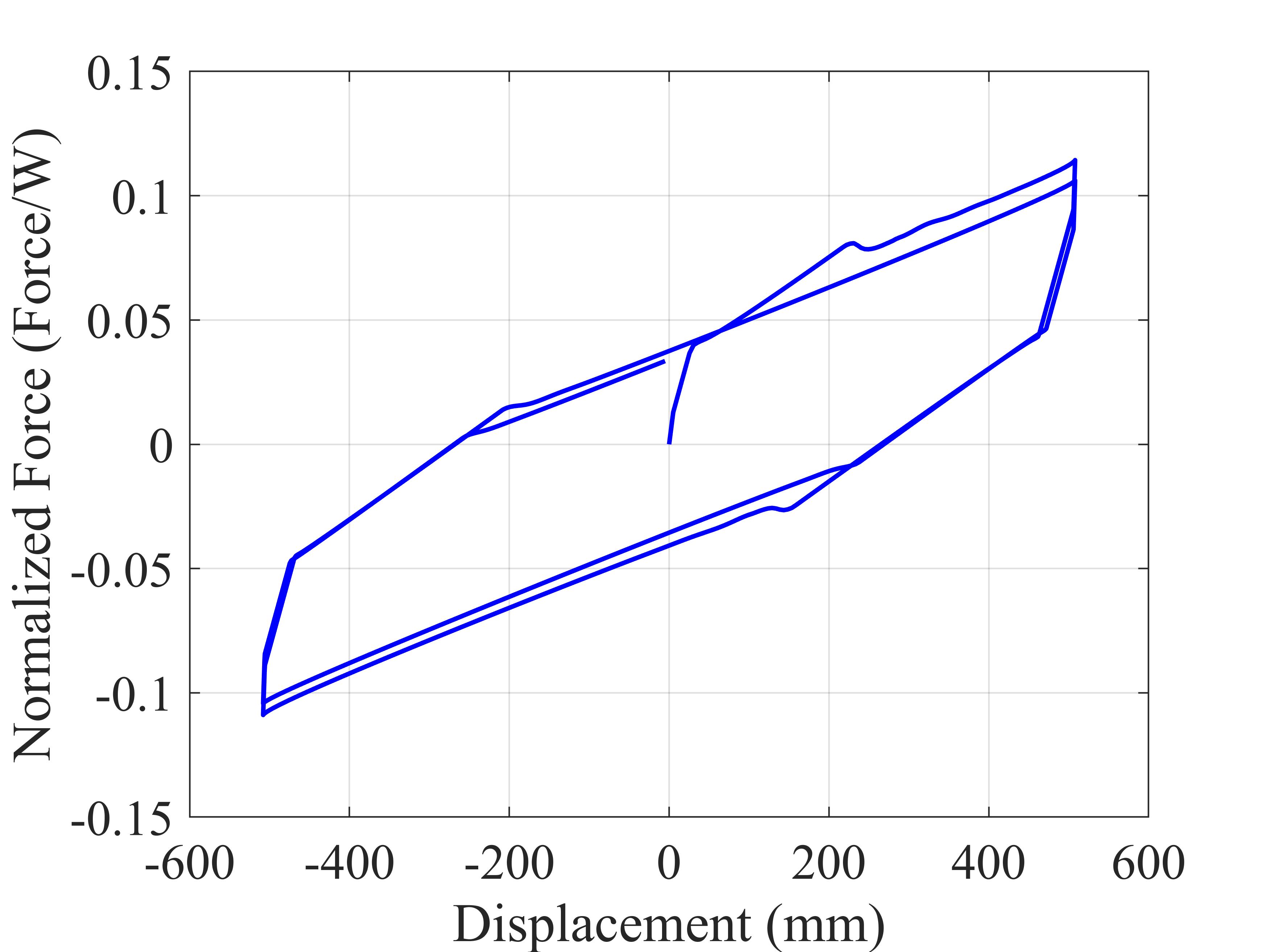
Fig. 3.1.10.32 Figure 3. Geometry of Triple FP bearing in accordance with OpenSees Commands
Command
element TripleFrictionPendulumX $eleTag $iNode $jNode $Tag1 $Tag2 $vertMatTag $rotZMatTag $rotXMatTag $rotYMatTag $kpFactor $kTFactor $kvFactor $Mu1 $Mu2 $Mu3 $L1 $L2 $L3 $d1_star $d2_star $d3_star $b1 $b2 $b3 $t2 $t3 $W $uy $kvt $minFv $Tol $refPressure1 $refPressure2 $refPressure3 $Diffusivity $Conductivity $Temperature0 $rateParameter $kTmodels $unit
Argument |
Type |
Description |
|---|---|---|
$eleTag |
integer |
Unique element object tag. |
$iNode $jNode |
integer integer |
End nodes. |
$Tag1 |
integer |
\(1\): for Approach 1 (suitable for all types of analysis) \(0\): for Approach 2 (1D displacement control analysis only) |
$Tag2 |
integer |
\(1\): for heat conduction theory for indefinite half space and indefinite heat source at the surface \(2\): for heat conduction theory of heated plate of finite depth over insulated space and indefinite heat source at the surface |
$vertMatTag |
float |
Pre-defined material tag for compression behavior of the bearing. |
$rotZMatTag $rotXMatTag $rotYMatTag |
integer integer integer |
Pre-defined material tags for rotational behavior about 3-axis, 1-axis and 2-axis, respectively. |
$kpFactor |
integer |
\(1\): if the coefficient of friction is a function of instantaneous axial pressure. \(k_{p}=0.7^{0.02(p-p_{0})}\) |
$kTFactor |
integer |
\(1\): if the coefficient of friction is a function of instantaneous temperature at the sliding surface. |
$kvFactor |
integer |
\(1\): if the coefficient of friction is a function of instantaneous velocity at the sliding surface. \(k_{v}=1-0.5e^{-av}\) |
$Mu1 $Mu2 $Mu3 |
float float float |
Reference friction coefficients, \(\mu_i\) |
$L1 $L2 $L3 |
float float float |
Effective radii, \(L_i = R_i – h_i\) |
$d1_star $d2_star $d3_star |
float float float |
Actual displacement capacity of sliding interfaces. \(d_i^* = L_i/R_i·d_i\), \(d_i\) = Nominal displacement capacity of each sliding interface. Displacement limit of the bearing is \(u_{limit} = 2d_1^* + d_2^* + d_3^* + b_2^*/2\), where \(b_2\) is a diameter of rigid slider. |
$b1 $b2 $b3 |
float float float |
Diameters of the rigid slider and the two inner slide plates. |
$t2 $t3 |
float float |
Thicknesses of concave plates. (Typical values are 50mm or larger). |
$W |
float |
Axial force used for the first trial of the first analysis step. |
$uy |
float |
Lateral displacement at which sliding initiates at a sliding interface (effective “yield displacement”). Recommended value = \(0.025\) to \(1 mm\). Smaller values may cause convergence problem or may slow the program execution. |
$kvt |
float |
Tension stiffness \(k_{vt}\) of the bearing. Use a small, non-zero value to avoid numerical problems. |
$minFv (≥ 0) |
float |
Minimum vertical compression force in the bearing used for computing the horizontal tangent stiffness matrix from the normalized tangent stiffness matrix of the element. |
$Tol |
float |
Relative tolerance for checking the convergence of the element. Recommended value = \(10^{-10}\) to \(10^{-3}\) |
$refPressure1 $refPressure2 $refPressure3 |
float float float |
Reference axial pressures (the bearing pressure under static loads) |
$Diffusivity |
float |
Thermal diffusivity of steel (unit: \(m^2/sec\)). (\(= 0.444·10^{-5}\) for stainless steel) |
$Conductivity |
float |
Thermal conductivity of steel (unit: \(W/m℃\)). (\(= 18\) for stainless steel) |
$Temperature0 |
float |
Initial temperature (\(℃\)). Use \(20℃\) as model of friction-temperature is based on \(20℃\). |
$rateparameter |
float |
Parameter in relationship of coefficient of friction and sliding velocity. (unit: \(sec/m\), \(100sec/m\) is used normally) |
$kTmodel |
integer |
Temperature-dependent friction models (3) \(1\): \(k_{T}=0.79(0.7^{0.02T}+0.40)\) (\(k_{T} = 1/2\) at \(200℃\)) \(2\): \(k_{T}=0.97(0.7^{0.029T}+0.22)\) (\(k_{T} = 1/3\) at \(200℃\)) \(3\): \(k_{T}=0.84(0.7^{0.0085T}+0.25)\) (\(k_{T} = 2/3\) at \(200℃\)) |
$unit |
integer |
Tag to identify the unit from the list below. \(1\): \(N, m, sec, ℃\) \(2\): \(kN, m, sec, ℃\) \(3\): \(N, mm, sec, ℃\) \(4\): \(kN, mm, sec, ℃\) \(5\): \(lb, in, sec, ℃\) \(6\): \(kip, in, sec, ℃\) \(7\): \(lb, ft, sec, ℃\) \(8\): \(kip, ft, sec, ℃\) |
Recorders
Typical Element Recorders
Typical recorders for two-node element are available in the TripleFrictionPendulumX element.
Recorder
Description
globalForce
global forces
localForce
local forces
basicForce
basic forces
basicDisplacement
basic displacements
TripleFrictionPendulumX Element Recorders
Subscript “i” of the response quantities in the following recorders refer to the numbering of the sliding interfaces, starting from bottom to top sliding interfaces.
Recorder
Description
compDisplacement
Displacements (\(u_i\)) and velocities (\(v_i\)) at each sliding surface in the x and y directions \((u_{2x}+u_{3x})/2\), \(u_{1x},u_{4x}\), \((u_{2y}+u_{3y})/2\), \(u_{1y}\), \(u_{4y}\), \((v_{2x}+v_{3x})/2\), \(v_{1x}\), \(v_{4x}\), \((v_{2y}+v_{3y})/2\), \(v_{1y}\), \(v_{4y}\) in accordance with Approach 1 (See Section 3 in [KimConstantinou2022].
Example: recorder Element<-file $fileName> -time<-ele ($ele1 $ele2…)>compDisplacement
Parameters
Temperatures at surface (\(T_{2,3}\), \(T_1\), \(T_4\)), Temperatures at depth \(t_1\), \(t_4\) (\(T_{1, t1}\), \(T_{4, t4}\)), coefficients of friction (\(\mu_{2,3}\), \(\mu_1\), \(\mu_4\)), heat fluxes (\(HeatFlux_{2,3}\), \(HeatFlux_{1}\), \(HeatFlux_4\)), pressure dependency factors (\(k_{p2,3}\), \(k_{p1}\), \(k_{p4}\)), temperature dependency factors (\(k_{T2,3}\), \(k_{T1}\), \(k_{T4}\)), and velocity dependency factors (\(k_{v2,3}\), \(k_{v1}\), \(k_{v4}\)).
Example: recorder Element<-file $fileName> -time<-ele ($ele1 $ele2…)>Parameters
Example
The following code computes results for the triple friction pendulum isolator “Configuration A” described in [KimConstantinou2023] subjected to constant load and lateral motion of 600mm amplitude at 5sec period over 10 cycles. A finite plate thickness of 20mm for both outer surfaces was specified.
Tcl Code
#############################################################################
#-------Department of Civil, Structural and Environmental Engineering-------#
#---------------------------University at Buffalo---------------------------#
# Modeling of Triple FP isolator (TripleFrictionPendulumX)                  #
# Written By: Hyun-Myung Kim (hkim59@buffalo.edu)                           #
# Date: May, 2024                                                           #
#############################################################################

# Units: N, m, sec
# Remove existing model
wipe

# Command manual example
#----------------------------------------------------------------------------
# User Defined Parameters
#----------------------------------------------------------------------------

# TFP Geomoetry of Configuration A (Kim and Constantinou, 2023 https://doi.org/10.1002/eqe.3797)
set L1 0.3937;                    # Effective radii (m)
set L2 3.7465;
set L3 3.7465;
set d1 0.0716;                    # Actual displacement capacity (m)
set d2 0.5043;
set d3 0.5043;
set b1 [expr 0.508];              # Diameter of the rigid slider and the two inner slide plate (m)
set b2 [expr 0.711];
set b3 [expr 0.711];
set r1 [expr $b1/2];              # Radius of of the rigid slider and the two inner slide plate (m)
set r2 [expr $b2/2];
set r3 [expr $b3/2];
set Thickness2 0.02;              # Thickness of concave plate (m)
set Thickness3 0.02;

set uy 0.001;                     # Yield displacement (m)
set kvc 8000000000.;              # Vertical compression stiffness (N/m)
set kvt 1.;                       # Vertical tension stiffness (N/m)
set minFv 0.1;                    # Minimum compression force in the bearing (N)

set g     9.81;                   # Gravity acceleration (m/s^2)
set P     13345e+03;              # Load on top of TFP
set Mass [expr $P/$g];            # Mass on top of TFP
set tol 1.e-5;                    # Relative tolerance for checking convergence

# Heat parameters
set Diffu 0.444e-5;               # Thermal diffusivity (m^2/sec)
set Conduct 18;                   # Thermal conductivity (W/m*Celsius)
set Temperature0 20;              # Initial temperature (Celsius)
set tagT2 2;                      # 1 = indefinite plate thickness / 2 = finite plate thickness

# Friction coefficients (reference)
set mu1 0.01;
set mu2 0.04;
set mu3 0.08;

# Reference Pressure
set Pref1 [expr $P/($r1*$r1*3.141592)];
set Pref2 [expr $P/($r2*$r2*3.141592)];
set Pref3 [expr $P/($r3*$r3*3.141592)];

#----------------------------------------------------------------------------
# Start of model generation
#----------------------------------------------------------------------------

#Create Model Builder
model basic -ndm 3 -ndf 6

# Create nodes
node 1 0 0 0; # End i
node 2 0 0 0; # End j

# Define single point constraints
fix 1     1 1 1 1 1 1;

# Define friction models
set tagTemp 1;
set tagVel 1;
set tagPres 0;
set velRate 100;
set kTmodel 1;                     # kT = 1/2 at 200 degree celsius

#----------------------------------------------------------------------------
# Bring material models and define element
#----------------------------------------------------------------------------

# Creating material for compression and rotation behaviors
uniaxialMaterial Elastic 1 $kvc;
uniaxialMaterial Elastic 2 10.;

set tagT 1;

# Define TripleFrictionPendulumX element
# element TripleFrictionPendulumX $eleTag $iNode $jNode $tagT $tagT2 $vertMatTag $rotZMatTag $rotXMatTag $rotYMatTag $tagPres $tagTemp $tagVel $mu1 $mu2 $mu3 $L1 $L2 $L3 $d1 $d2 $d3 $b1 $b2 $b3 $Thickness2 $Thickness3 $W $uy $kvt $minFv $tol $Pref1 $Pref2 $Pref3 $Diffu $Conduct $Temperature0 $velRate $kTmodel $unit
element TripleFrictionPendulumX 1 1 2 $tagT $tagT2 1 2 2 2 $tagPres $tagTemp $tagVel $mu1 $mu2 $mu3 $L1 $L2 $L3 $d1 $d2 $d3 $b1 $b2 $b3 $Thickness2 $Thickness3 $P $uy $kvt $minFv $tol $Pref1 $Pref2 $Pref3 $Diffu $Conduct $Temperature0 $velRate $kTmodel 1;

#----------------------------------------------------------------------------
# Apply gravity load
#----------------------------------------------------------------------------

#Create a plain load pattern with linear timeseries
pattern Plain 1 "Linear" {

        load 2 0. 0. -[expr $P] 0.0 0.0 0.0
}

#----------------------------------------------------------------------------
# Start of analysis generation (Gravity)
#----------------------------------------------------------------------------

system BandSPD
constraints Transformation
numberer RCM
test NormDispIncr 1.0e-15 10 3
algorithm Newton
integrator LoadControl 0.1
analysis Static

#----------------------------------------------------------------------------
# Analysis (Gravity)
#----------------------------------------------------------------------------

analyze 10
puts "Gravity analysis completed SUCCESSFULLY";

#----------------------------------------------------------------------------
# Start of analysis generation
# (Sinusoidal; Ten cycles of 5s period and 600mm amplitude)
#----------------------------------------------------------------------------

loadConst -time 0.0

# analysis time step
set dt [expr 0.008]

# excitation time step
set dt1 [expr 0.001]

#timeSeries Trig $tag $tStart $tEnd $period <-factor $cFactor> <-shift $shift>
timeSeries Trig 11 $dt 50 5 -factor 0.6 -shift 0

pattern MultiSupport 2 {
groundMotion 1 Plain -disp 11
# Node, direction, GMtag
imposedMotion 2 2 1
}

#----------------------------------------------------------------------------
# Start of recorder generation (Sinusoidal)
#----------------------------------------------------------------------------

# Set up recorder
set OutDir                EXAMPLE;                       # Output folder

set OutFile1      TEMPERATURE_FINITE_DEPTH.txt;
set OutFile2      DISP_FINITE_DEPTH.txt;
set OutFile3      FORCE_FINITE_DEPTH.txt;
set OutFile4      COMPDISP_FINITE_DEPTH.txt;

file mkdir $OutDir;
recorder Element -file $OutDir/$OutFile1 -time -ele 1 Parameters;
recorder Node -file $OutDir/$OutFile2 -time -nodes 2 -dof 1 2 3 disp;
recorder Element -file $OutDir/$OutFile3 -time -ele 1 basicForce;
recorder Element -file $OutDir/$OutFile4 -time -ele 1 compDisplacement;

#----------------------------------------------------------------------------
# Analysis (Sinusoidal)
#----------------------------------------------------------------------------

system SparseGeneral
constraints Transformation
test NormDispIncr 1.0e-5 20 0
algorithm Newton
numberer Plain
integrator Newmark 0.5 0.25
analysis Transient

# set some variables
set tFinal [expr 50]
set tCurrent [getTime]
set ok 0

# Perform the transient analysis
while {$ok == 0 && $tCurrent < $tFinal} {
    set ok [analyze 1 $dt]
    set tCurrent [getTime]
}

# Print a message to indicate if analysis succesfull or not
if {$ok == 0} {
   puts "Transient analysis completed SUCCESSFULLY";
} else {
  puts "Transient analysis completed FAILED";
}
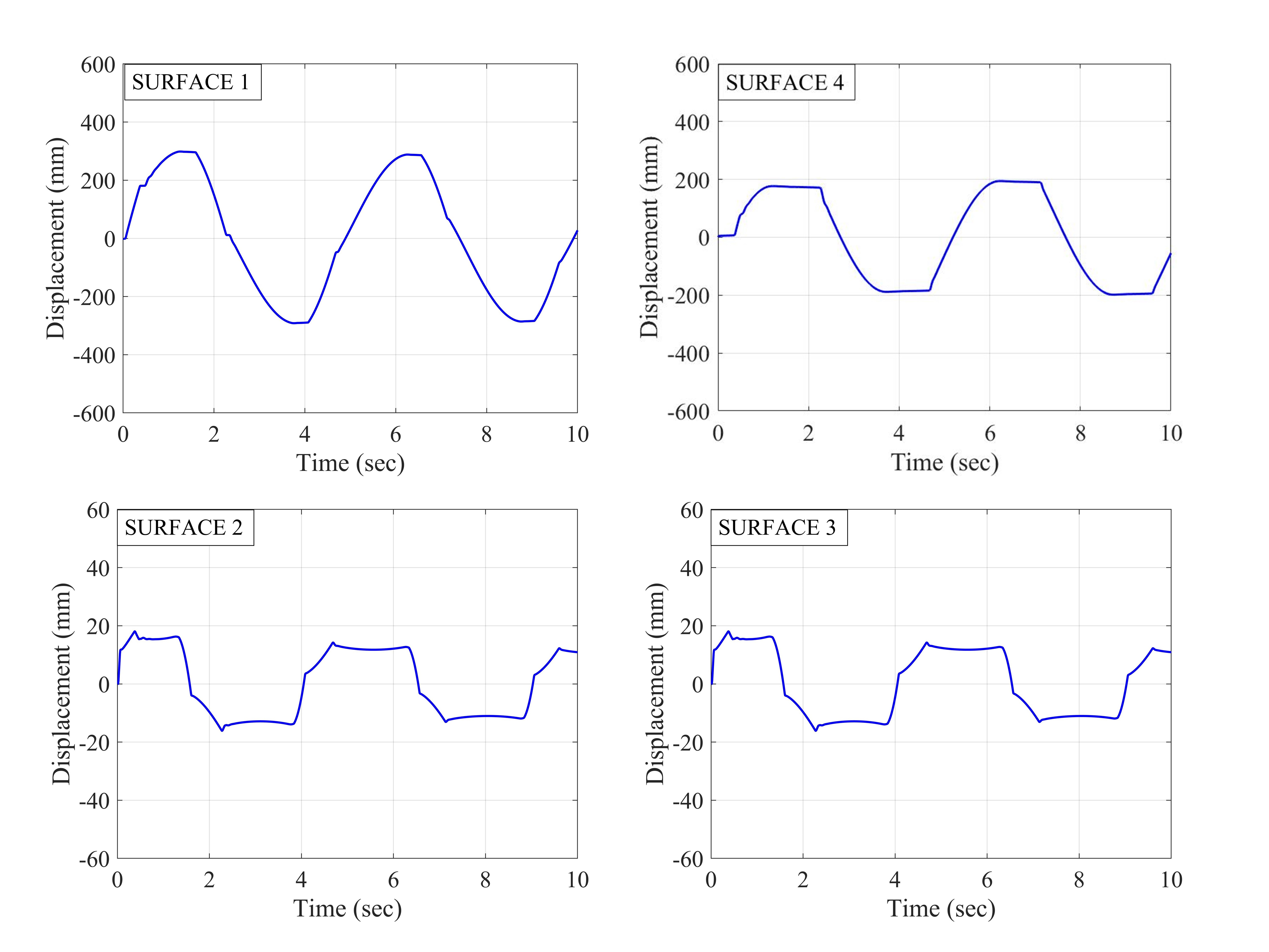
Fig. 3.1.10.33 Figure 4. Force-displacement loop
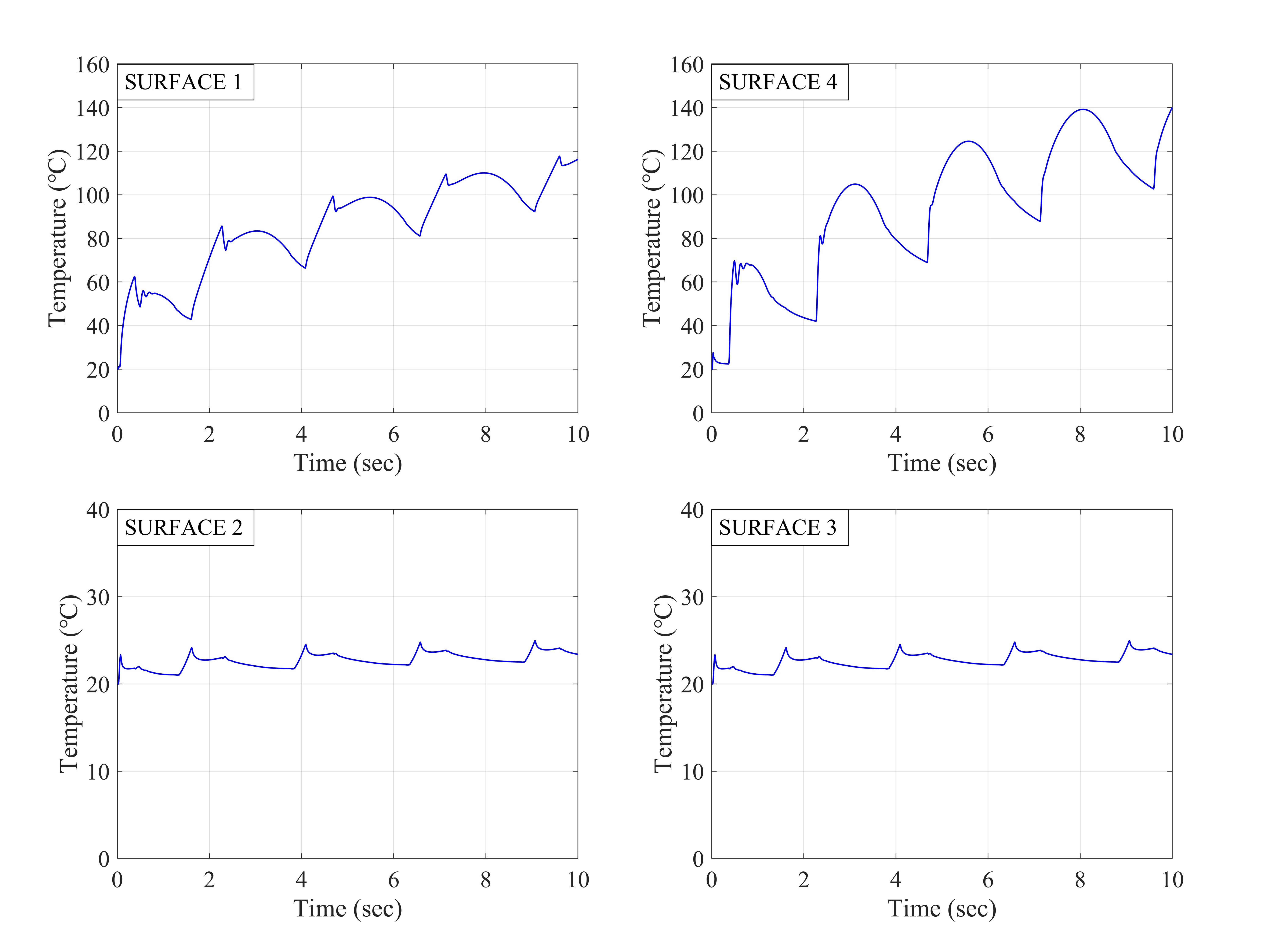
Fig. 3.1.10.34 Figure 5. Displacement histories at sliding surfaces
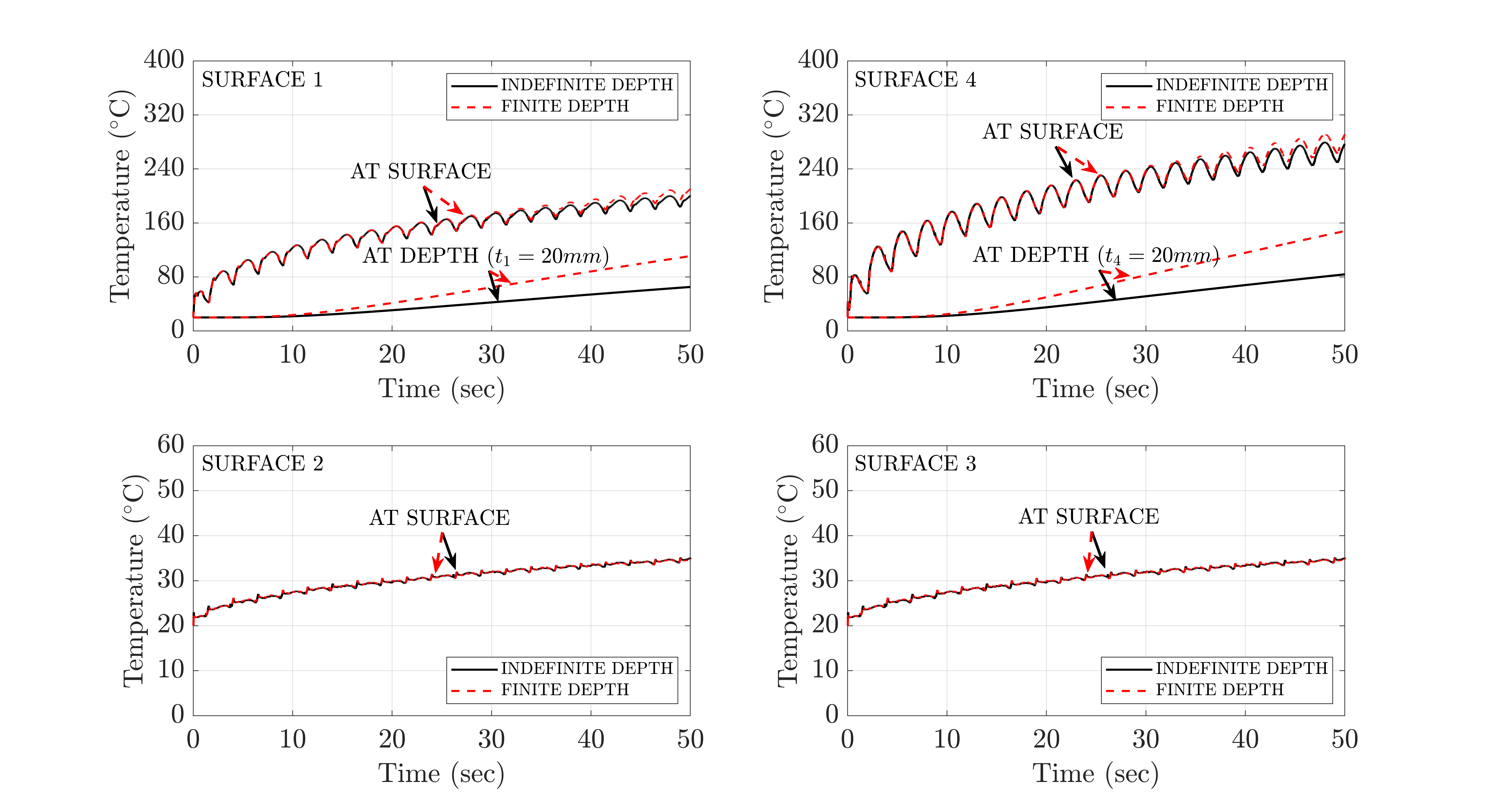
Fig. 3.1.10.35 Figure 6. Temperature histories at sliding surfaces
Reference
Dao, N. D., Ryan, K. L., Sato, E. and Sasaki, T. (2013). “Predicting the displacement of triple pendulum bearings in a full-scale shaking experiment using a three-dimensional element”, Earthquake Engineering & Structural Dynamics, 42(11), 1677-1695. https://doi.org/10.1002/eqe.2293.
“Modeling triple friction pendulum bearings in program OpenSees including frictional heating effects”, Report No. MCEER-22-0001, Multidisciplinary Center for Earthquake Engineering Research, Buffalo, NY.
“Modeling frictional heating effects in triple friction pendulum isolators”, Earthquake Engineering & Structural Dynamics, 52(4), 979–997. https://doi.org/10.1002/eqe.3797.
“Validity of models for frictional heating in sliding isolators”, Earthquake Engineering & Structural Dynamics, 53(3), 1308–1325. https://doi.org/10.1002/eqe.4067.
“Characterizing friction in sliding isolation bearings”, Earthquake Engineering & Structural Dynamics, 44(9), 1409-1425. https://doi.org/10.1002/eqe.2524.
Code Developed by: Hyun-Myung Kim and Michael C. Constantinou, University at Buffalo
For bug reporting, please contact: Hyun-Myung Kim (hkim59@buffalo.edu)