3.1.10.20. Gradient Inelastic (GI) Beam-Column Element
This command is used to construct a gradientInelasticBeamColumn element object, which is based on a force/flexibility-based (FB) gradient inelastic (GI) element formulation with an iterative solution algorithm. The GI element formulation is based on the GI beam theory, which eliminates the strain localization and response objectivity problems by utilizing a set of gradient-based nonlocality relations that ensure the continuity of section strains (e.g., curvature) over the element length, upon the occurrence of softening at any section. The GI element does not necessitate any certain form of constitutive relations and permits users to use the same constitutive relations used in conventional FB element formulations. Moreover, the number of integration points in the GI element is not fixed and it could produce section strain (e.g., curvature) distributions with high resolutions.
From the user’s perspective, the gradientInelasticBeamColumn element has similar input to other force-based fiber elements’ and the only additional parameter that this element requires is a characteristic length, lc, which controls the spread of plasticity/damage in the vicinity of a softening location. In the simulation of RC beams/columns, this parameter can be taken equal to the plastic hinge length. If lc equals zero, the GI beam element formulation turns into a conventional FB element formulation (i.e., as if the classical beam theory is used).
For more information about the GI element formulation, please refer to this post and the references at the end of this page.
TCL ELEMENT COMMAND
For both 2D and 3D problems:
- element gradientInelasticBeamColumn $eleTag $iNode $jNode $numIntgrPts $endSecTag1 $intSecTag $endSecTag2 $lambda1 $lambda2 $lc $transfTag <-integration integrType> <-iter $maxIter $minTol $maxTol>
The required arguments are:
Argument |
Type |
Description |
|---|---|---|
$eleTag |
integer |
unique element object tag |
$iNode $jNode |
integer |
end nodes |
$numIntgrPts |
integer |
total number of integration points - recommended to exceed (1.5L ⁄ lc + 1) when default integration method is used (L = beam length and lc = characteristic length) |
$endSecTag1 |
integer |
near-end part’s section tag (Fig. 1) |
$intSecTag |
integer |
intermediate part’s sections tag (Fig. 1) |
$endSecTag2 |
integer |
far-end part’s section tag (Fig. 1) |
$lambda1 |
float |
fraction of beam length (L) at near end represented by $endSecTag1 (Fig. 1) |
$lambda2 |
float |
fraction of beam length (L) at far end represented by $endSecTag2 (Fig. 1). Note that $lambda1 + $lambda2 should be smaller than unity |
$lc |
float |
characteristic length - it can be taken as plastic hinge length |
$transfTag |
integer |
identifier for previously-defined coordinate-transformation (CrdTransf) object |
The optional arguments are:
Argument |
Sub-argument |
Type |
Description |
|---|---|---|---|
-integration |
used to select integration type |
||
integrType |
string |
Options: ‘NewtonCotes’, ‘Simpson’, or ‘Trapezoidal’ (default: ‘Simpson’) – if Simpson’s rule is used, $numIntgrPts should be an odd number |
|
-iter |
used to set iterative solution algorithm parameters |
||
$maxIter |
integer |
maximum number of iterations (default: 50) |
|
$minTol |
float |
minimum tolerance (default: 1E-10) |
|
$maxTol |
float |
maximum tolerance (default: 1E-8) |
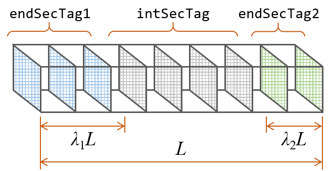
Fig. 3.1.10.2 Fig. 1: Assignment of pre-defined sections to integration points at different parts of element
PYTHON ELEMENT COMMAND
For both 2D and 3D problems:
- element('gradientInelasticBeamColumn', $eleTag, $iNode, $jNode, $transfTag, $integrTag, $lc, '-iter', $maxIter, $minTol, $maxTol)
The required arguments are:
Argument |
Type |
Description |
|---|---|---|
$eleTag |
integer |
unique element object tag |
$iNode $jNode |
integer |
end nodes |
$transfTag |
integer |
identifier for previously-defined coordinate-transformation (CrdTransf) object |
$integrTag |
integer |
identifier for previously-defined beam integration object |
$lc |
float |
characteristic length - it can be taken as plastic hinge length |
The optional arguments are:
Argument |
Sub-argument |
Type |
Description |
|---|---|---|---|
-iter |
used to set iterative solution algorithm parameters |
||
$maxIter |
integer |
maximum number of iterations (default: 50) |
|
$minTol |
float |
minimum tolerance (default: 1E-10) |
|
$maxTol |
float |
maximum tolerance (default: 1E-8) |
NOTES:
The beam integration method shall be trapezoidal, Simpson’s, or Newton-Cotes.
The total number of integration points is recommended to exceed (1.5L ⁄ lc + 1) when Simpson’s and Newton-Cotes integration methods are used, and (3L ⁄ lc + 1) when trapezoidal integration method is used (L = beam length and lc = characteristic length).
ELEMENT RECORDERS
Valid queries to the gradientInelasticBeamColumn element when creating an ElementRecorder object are:
force or globalForce
localForce
basicForce
section $sectionNumber $arg1 $arg2 … (note: $sectionNumer is integer 1 through $numIntegrPts)
dampingForce
nonlocalStrain (note: this would provide the macroscopic section strains at all integration points).
NOTE: Section responses shall be expressed in terms of section forces/moments vs. macroscopic section strains/curvatures and the section strains/curvature distributions shall be obtained from macroscopic section strains/curvatures. The section strains/curvatures obtained via “section $sectionNumber deformations” are material section strains (i.e. internal parameters) and shall not be used in place of macroscopic section strains.
TCL EXAMPLE
The element command for the GI element simulating the RC beam in Fig. 2, assuming L = 5, λ1 = 0.2, λ2 = 0.3, and lc = 0.5, while the tag for the predefined coordinate-transformation object is 20, may take the form below:
element gradientInelasticBeamColumn 10 1 2 21 1 2 1 0.2 0.3 0.5 20 -integration Simpson -iter 20 1E-8 1E-6;
Observations/recommendations:
The number of integration points, N, was selected to be equal to 21 to achieve lc ⁄ Δx ≥ 1.5 – or more simply, N ≥ 1.5L ⁄ lc + 1. This condition has been found to result in discretization convergence from most common applications. Yet, users are recommended to perform their own discretization convergence study, as dictated by their applications, and as they would do for conventional force-based elements.
As illustrated in Fig. 2, section tags 1 and 2 refer to fiber sections representing the RC beam’s cross-sections A-A and B-B. These fiber sections are defined with two different longitudinal reinforcement layouts and two different confined concrete material models because of their transverse reinforcement differences.
Each member shall be modeled by a single gradientInelasticBeamColumn element. If two or more elements are used, they are recommended to be larger than 4lc.
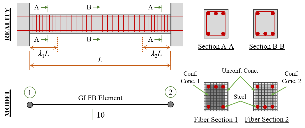
Fig. 3.1.10.3 Fig. 2: GI element application example
PYTHON EXAMPLE
The element command for the GI element simulating the RC beam in Fig. 2, assuming lc = 0.5, while the tag for the predefined coordinate-transformation and beam integration objects are 20 and 10, respectively, may take the form below:
element('gradientInelasticBeamColumn', 10, 1, 2, 20, 10, 0.5, '-iter', 20, 1E-8, 1E-6)
REFERENCES:
Sideris, P., Salehi, M. (2016). “A Gradient-Inelastic Flexibility-based Frame Element Formulation.” Journal of Engineering Mechanics, 142(7): 04016039.
Salehi, M., Sideris, P. (2017). “Refined Gradient Inelastic Flexibility-Based Formulation for Members Subjected to Arbitrary Loading.” Journal of Engineering Mechanics, 143(9): 04017090.
Salehi, M., Sideris, P., Liel, A.B. (2017). “Seismic Collapse Analysis of RC Framed Structures using the Gradient Inelastic Force-Based Element Formulation.” 16th World Conference on Earthquake Engineering (16WCEE), Santiago Chile, January 9-13.
Salehi, M., Sideris, P., Liel, A.B. (2020). “Assessing Damage and Collapse Capacity of Reinforced Concrete Structures Using the Gradient Inelastic Beam Element Formulation.” Engineering Structures, 225: 111290.
When citing the GI element, please use the first two articles
Code developed by: Mohammad Salehi |msalehi2004| (Rice University) and Petros Sideris |psideris| (Texas A&M University)