3.1.10.93. RockingBC Element
This command is used to construct a RockingBC element. This element can be used to describe the rocking motion of 2d deformable bodies, either elastic or inelastic, under static or dynamic loading. Apart from the deformability along the length of the member, the element is able to account for deformability near the contact area, where nonlinear stress distributions develop and sections do not remain plane. Furthermore, the element is able to account for constraints along the length of the rocking member imposed by other structural members, as well as sliding and upthrow. More information about the theory and usage of the element can be found in the References below.
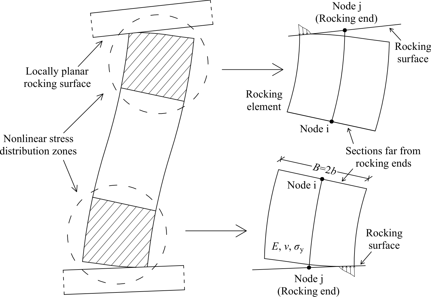
Fig. 3.1.10.41 RockingBC element
Command
element RockingBC $eleTag $iNode $jNode $Nw $E $nu $sy $B $w $mu <-convlim $convlim> <-useshear $useshear> <-blevery $blevery> <-useUelNM $useUelNM> <-usecomstiff $usecomstiff> <-af $af> <-aflim $aflim> <-convlimmult $convlimmult> <-maxtries $maxtries> <-NlimN $NlimN> <-NlimT $NlimT> <-Dtlim $Dtlim> <-errorifNexceeds $errorifNexceeds>
Argument |
Type |
Description |
|---|---|---|
$eleTag |
integer |
unique element object tag |
$iNode |
integer |
the node of the element with conventional behavior, fixed with the other member |
$jNode |
integer |
the node of the element corresponding to the rocking end (Note that the dofs of this node correspond to the motion of the rocking base and not to the end of the rocking member) |
$Nw |
integer |
number of control points used for the discretization of the rocking interface |
$E |
float |
modulus of elasticity |
$nu |
float |
Poisson ratio |
$sy |
float |
yield stress (must be negative): An elastic - perfectly plastic material behavior is adopted for the rocking interface, where the inelastic deformations are considered irreversible |
$B |
float |
member width |
$w |
float |
member thickness |
$mu |
float |
friction coefficient at the rocking interface: If the value 0 is used, there is no sliding and the relative displacement of the body with respect to the rocking base is due to upthrow only. |
$convlim |
float |
convergence limit for the norm of the difference of the control point displacements from the target ones at the rocking end of the member (default value=1.0e-14) |
$useshear |
integer |
If nonzero, the contribution of the partial loading of the shear stresses is taken into account. As explained in the relevant reference [4], this option creates problems when used in dynamic analyses (default value=0) |
$blevery |
integer |
Number of steps after which a bilinearization of the stress and plastic displacement distributions across the rocking interface is performed. This greatly accelerates dynamic analyses, which involve many steps. When 0, no bilinearization is performed. (default value=1) |
$useUelNM |
integer |
If the value 0 is used, the contribution of the partial loading of the rocking interface is calculated using the exact stress distributions. This, however, is computationally inefficient and does not allow the aforementioned distribution bilinearization. Else, the integrals of the stress distribution at each rocking interface interval are used instead, which produces practically indistinguishable results. (default value=1) |
$usecomstiff |
integer |
If the value 0 is used, the initial trial solution of each step is determined from the previous stiffness and previous trial solution, even if convergence failed previously. If -1, the inital trial solution is the same as the last committed solution. Else, the initial trial solution is determined from the committed stiffness and committed solution. (default value=0) |
$af $aflim $convlimmult $maxtries |
float float float integer |
variables controlling convergence tries - see Note 2 below (corresponding default values=1.0, 0.4, 1.0, 100) |
$NlimN $NlimT $Dtlim $errorifNexceeds |
float float float integer |
variables controlling the rate of change of the member axial force, applicable when performing a dynamic analysis and especially useful when impacts are expected - see Note 3 below (corresponding default values=0.1, 10.0, 1.0e-8, 0) |
Notes
For dynamic analyses, the element uses a damping formulation similar to the current-stiffness-proportional damping. For this reason, only the $betaKcurr value defined in Rayleigh damping is taken into account by the element.
The rocking motion is highly nonlinear and as such, convergence problems sometimes occur during state determination. In order to overcome such problems, in the current version of the element, the following variables and strategies are used: During convergence iterations, the trial vector of stresses/displacements at the control points W is incremented $af times the usual increment calculated using the derivatives and one may set $af lower than 1.0 to achieve better convergence, with the cost of slower convergence. However, since $af=1.0 is the usually the optimum value, this value is suggested and $af is lowered automatically as explained next. The maximum number of tries allowed for each convergence stage is set to $maxtries/$af^3, during which the norm of the difference of the control point displacements at the rocking interface from the target ones must become lower than $convlim. If such convergence is not possible the first time, $af is halved and the convergence limit is set to $convlimmult*$convlim and convergence is tested again. The second time, the same $af and convergence limit are used, but the initial trial vector W is set to zero. If convergence is again not possible, $af is subsequently halved and the convergence limit is constantly multiplied with $convlimmult, until $af becomes lower than $aflim, when an error is thrown.
In order for the element to produce accurate results in dynamic problems involving impacts, the rate of change of the axial force of the element must be controlled, so that it does not exceed a predefined limit each step. This allows for a more accurate calculation of the damping forces, which are very large in case of impacts. If variable $errorifNexceeds is set to a nonzero value, the element throws an error to the general finite element framework if such exceedance occurs. The last value of the member axial force before the dynamic analysis is stored, which is used to calculate the ratio of the increment in the deformation-inducing axial force with respect to the last static axial force and the ratio of the increment in the total (deformation-inducing & damping) axial force with respect to the last static axial force. These values should not exceed $NlimN and $NlimT, respectively, or an error is thrown, so that the algorithm which calls the dynamic analysis may lower the timestep. If the current timestep used is lower than $Dtlim, an error is not thrown, which may be used when a further timestep reduction is considered impossible without causing numerical problems.
The following recorders can be used with the element:
Recorder |
Description |
|---|---|
force or globalForce |
global forces |
localForce |
local forces |
basicForce |
basic (corotational system) forces |
localDisplacements |
local system displacements |
sL or slip |
relative slip between the rocking body end and the rocking interface |
forceratioNmax |
maximum ratio of the increment in the deformation-inducing axial force in a dynamic analysis with respect to the last value of the axial force before the dynamic analysis |
forceratioTmax |
maximum ratio of the increment in the total (deformation-inducing & damping) axial force in a dynamic analysis with respect to the last value of the axial force before the dynamic analysis |
other (arbitrary) |
This option is used when the stress and plastic displacement distributions across the rocking interface are required at each step. The former are recorded in files other_Ys (coordinates) and other_S (stress values), while the latter in files other_Yup (coordinates) and other_Up (plastic displacement values). |
Example
An example file can be located at https://github.com/OpenSees/OpenSees/tree/master/EXAMPLES/ExampleScripts/RockingBC.tcl
References
Avgenakis E. and Psycharis I.N. (2017) “Modeling of Rocking Elastic Flexible Bodies under Static Loading Considering the Nonlinear Stress Distribution at Their Base.” Journal of Structural Engineering 143(7): 04017051.
Avgenakis E. and Psycharis I.N. (2019) “Determination of the nonlinear displacement distribution of the semi-infinite strip–Application to deformable rocking bodies.” International Journal of Solids and Structures, 170, 22-37.
Avgenakis E. and Psycharis I.N. (2020) “Modeling of inelastic rocking bodies under cyclic loading.” Journal of Engineering Mechanics 146(4): 04020020.
Avgenakis E. and Psycharis I.N. (2020) “An integrated macroelement formulation for the dynamic response of inelastic deformable rocking bodies.” Earthquake Engineering and Structural Dynamics, 49(11), 1072-1094.
Code Developed by: Evangelos Avgenakis and Ioannis N. Psycharis, School of Civil Engineering, National Technical University of Athens, Greece